Description
The hurricane tie series features various configurations of wind and seismic ties for trusses and rafters.
H16 — the H16 series has a presloped seat of 5/12 for double trusses. The presloped seat of the H16 provides for a tight fit and reduced deflection. The strap length provides for various truss height up to a maximum of 13 1/2" (H16 series). Minimum heel height for H16 series is 4".
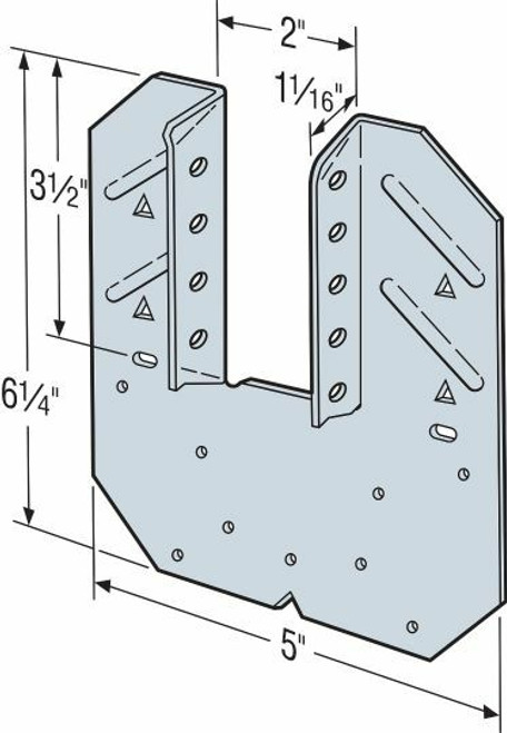
HGA10 — the HGA10 attaches to gable trusses and provides good lateral wind resistance.
HS24 — the HS24 attaches the bottom chord of a truss or rafter at pitches from 0/12 to 4/12 to double 2x4 top plates. Double-shear nailing allows for higher lateral resistance.
Material
- See table
Finish
- Galvanized (G90). Selected products available in stainless steel or ZMAX® coating. See Corrosion Information.
Installation
- Use all specified fasteners; see General Notes.
- Hurricane ties can be installed with flanges facing inward or outward.
- H2.5T, H 3 and H6 ties are shipped in equal quantities of right and left versions (right versions shown).
- Hurricane ties do not replace solid blocking.
- When installing ties on plated trusses (on the side opposite the truss plate) do not fasten through the truss plate from behind. This can force the truss plate off of the truss and compromise truss performance.
- H10A optional nailing to connect shear blocking, use 0.131" x 2 1/2" nails. Slots allow maximum field bending up to a pitch of 6:12, use H10A sloped loads for field-bent installation.
- HS24 requires slant nailing only when bottom chord of truss or rafter has no slope.
- See also H seismic and hurricane ties for masonry applications.
Ordering Information
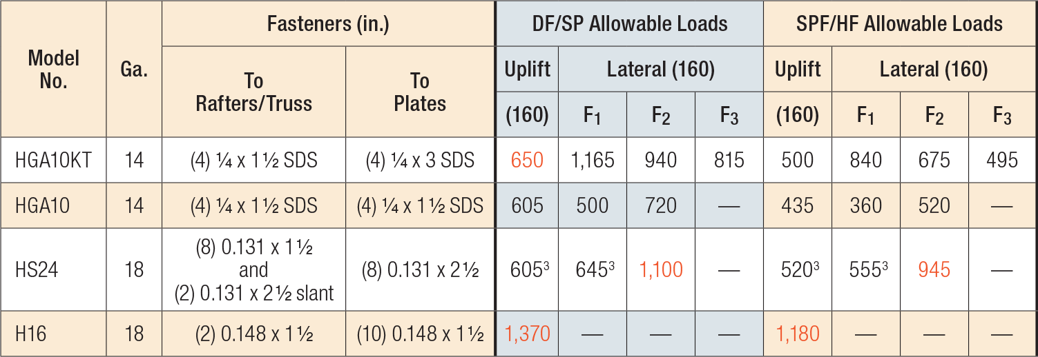
- HGA10KT: sold as a kit with (10) HGA10 connectors. Strong-Drive® SDS Heavy-Duty Connector screws are included.
- Additional screws sold separately to install with all SDS25112 screws.

- See General Notes for Straps and Ties.
- When cross-grain bending or cross-grain tension cannot be avoided in the members, mechanical reinforcement to resist such forces shall be considered by the Designer.
- HS24 DF/SP allowable loads without slant nailing are 605 lb. (uplift), 590 lb. (F1), 640 lb. (F2). For SPF/HF loads multiply these values by 0.86.
- Allowable loads in the F1 direction are not intended to replace diaphragm boundary members or prevent cross-grain bending of the truss or rafter members. Additional shear transfer elements shall be considered where there may be effects of cross-grain bending or tension.
- Fasteners: Nail dimensions in the table are diameter by length. SDS screws are Simpson Strong-Tie® Strong-Drive® screws. For additional information, see Fastener Types and Sizes Specified for Simpson Strong-Tie Connectors.
Extra Information
Brand:
Simpson Strong-Tie
Weight:
1.10 LBS


