Description
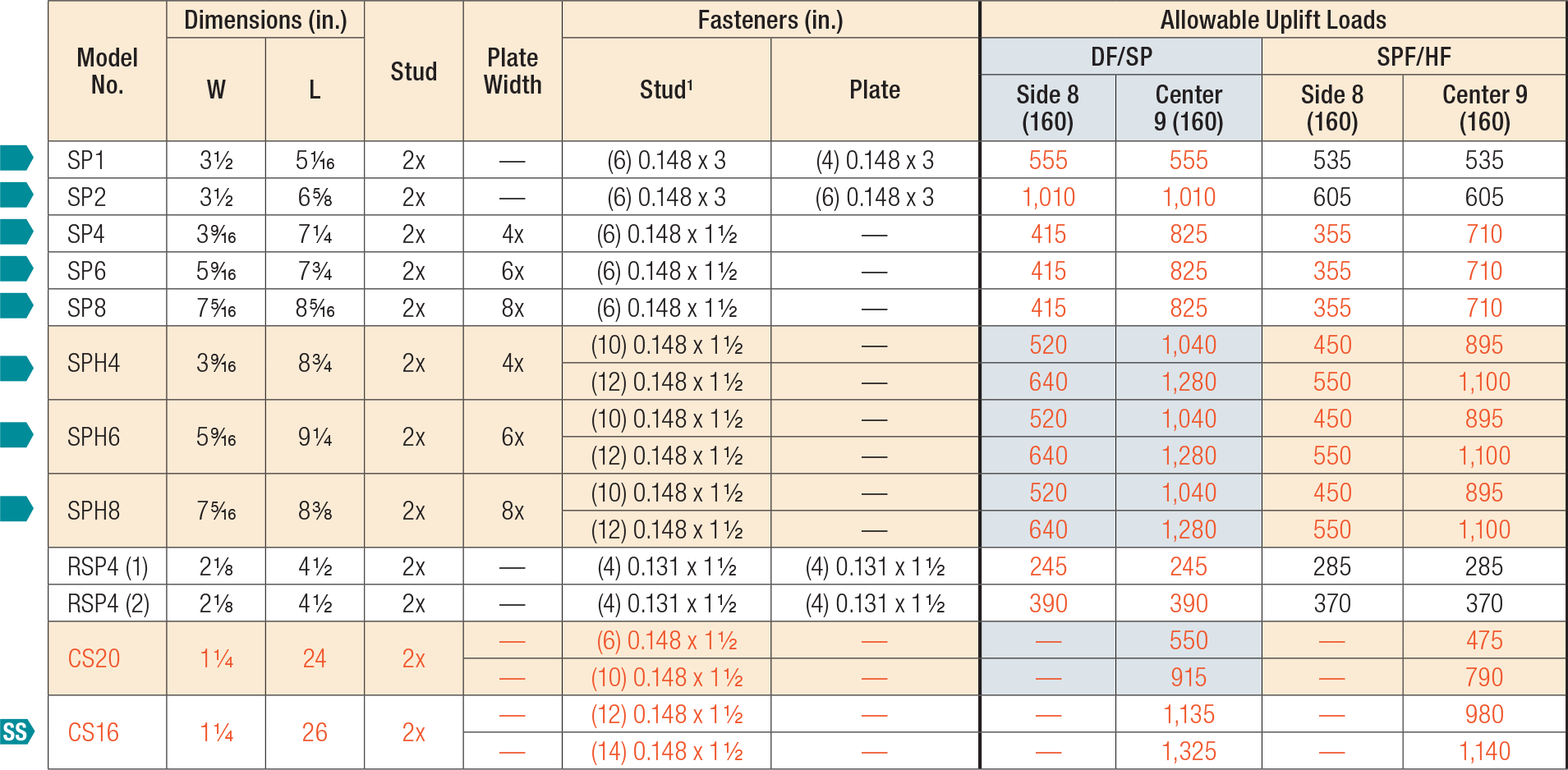
The stud plate tie series offers general solutions for connecting the stud to the top and bottom plates. All models can be used to make a connection to either the top or bottom plate, and several are suitable for double top plates and studs.
Material
- DSP/SSP/SPH — 18 gauge; TSP/CS16 — 16 gauge; all others — 20 gauge
Finish
- Galvanized. Some products available in ZMAX® coating. See Corrosion Information.
Installation
- Use all specified fasteners; see General Notes.
- TSP/DSP/SSP — sill plate installation: fill all round holes.
- TSP/DSP/SSP — top plate installation: fill all round and triangle holes.
- SP1/SP2 — one of the 0.148" x 3" stud nails is driven at a 45° angle through the stud into the plate.
- CS — slide the CS16 or CS20 strap underneath the mudsill with the appropriate length of strap protruding from the inside of the mudsill. See illustration for more details.
- Each bend in the strap must be tight, and the strap must sit flush against the edge of the mudsill and the stud or sheathing
- Bend strap one time only
Load Tables
These products are available with additional corrosion protection. Additional products on this page may also be available with this option, check with Simpson Strong-Tie for details.
For stainless-steel fasteners, see Fastener Types and Sizes Specified for Simpson Strong-Tie Connectors.
Many of these products are approved for installation with Strong-Drive® SD Connector screws.

- See General Notes for Straps and Ties.
- SP1/SP2 — drive one stud nail at an angle through the stud into the plate to achieve the table load (see illustration).
- RSP4 — see Installation details (1) and (2) for reference.
- RSP4 — F2 is 225 lb. for Installation 1 and 245 lb for Installation 2. F1 load is 165 lb. for both installations.
- Maximum load for SPH in southern yellow pine is 1,415 lb. for center loading and 710 lb. for side loading.
- When cross-grain bending or cross-grain tension cannot be avoided in the members, mechanical reinforcement to resist such forces shall be considered by the Designer.
- For retrofit application, use CS16 and CS20. Total length of strap is listed.
- Use Side (eccentric) load when uplift loads are applied to only one face of the top plate.
- Use Center (concentric) loads when uplift loads are applied at the centerline of the top plate, or where equal loads are applied to both sides of the top plate. Center loads should also be used for stud-to-bottom plate loads.
- Fasteners: Nail dimensions in the table are listed diameter by length. For additional information, see Fastener Types and Sizes Specified for Simpson Strong-Tie Connectors.

- See General Notes for Straps and Ties.
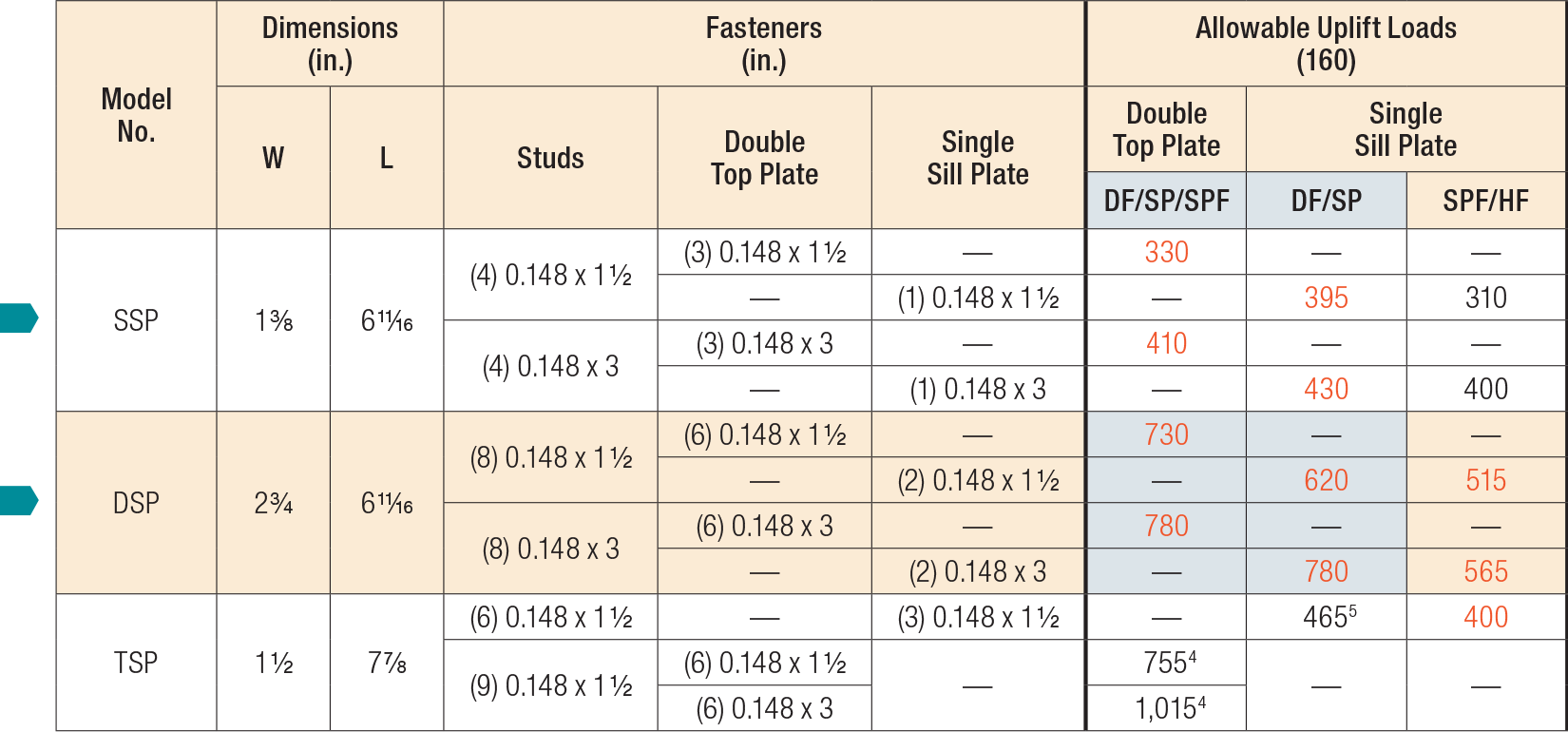
- When cross-grain bending or cross-grain tension cannot be avoided in the members, mechanical reinforcement to resist such forces shall be considered by the Designer.
- Allowable loads for DSP installed to a rim board are 620 lb. (DF/SP) and 515 lb. (SPF/HF).
- Noted values apply only to DF/SP members. For SPF values, multiply by 0.86.
- Southern pine allowable uplift load is 520 lb.
- Fasteners: Nail dimensions in the table are listed diameter by length. For additional information, see Fastener Types and Sizes Specified for Simpson Strong-Tie Connectors.
Load Values with Strong-Drive® SD Connector Screws Model No. Fasteners DF/SP Allowable Loads SPF/HF Allowable Loads To Rafters/ Truss To Plates/Base To Studs/Post Uplift Lateral Uplift Lateral (160) F1 (160) F2 (160) (160) F1 (160) F2 (160) - H connector loads based on installation to double top plate.
- Uplift load for the H4 stud to bottom plate installation is 415 lbs for DF/SP and 355 lbs for SPF/HF.
- Uplift load for the H8 stud to bottom plate installation is 380 lbs for DF/SP and 325 lbs for SPF/HF.
RSP4(1) - 4-SD9112 4-SD9112 520 205 190 450 175 165 RSP4(2) - 4-SD9112 4-SD9112 520 275 255 450 235 220


