


Description
The embedded truss anchor series provides an engineered method to properly attach roof trusses to concrete and masonry walls. The products are designed with staggered nail patterns for greater uplift resistance. Information regarding the use of two anchors on single- and multi-ply trusses is included.
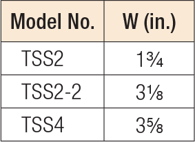
Simpson Strong-Tie provides two different moisture barrier plates between the concrete/masonry and truss. The TSS is a preassembled, companion product of the META. The TBP8 seat plate also provides a moisture barrier installed prior to truss placement. The seat plate is installed with prongs, instead of fasteners.
The DETAL20 is a high-capacity embedded truss anchor for attachment of single-ply trusses to concrete and masonry walls. It combines dual embedded anchors with a structural moisture-barrier seat that is partially embedded in the concrete or grout. This seat serves to protect the truss and also provides additional lateral and uplift capacity. The embedded anchors are preattached to the moisture barrier through slots that allow for a slight amount of adjustability, providing flexibility during installation to avoid rebar. The moisture-barrier seat includes tabs at each end for optional attachment to the form board in concrete tie-beam applications.
Material
- HHETA — 14 gauge; HETA — 16 gauge; HETAL — strap 16 gauge, truss seat 18 gauge; META — 18 gauge; TSS/TBP8 — 22 gauge; DETAL — 16 gauge (barrier — 18 gauge)
Finish
- Galvanized. Some products available in ZMAX® coating. See Corrosion Information.
Installation
- Use all specified fasteners; see General Notes.
- The META, HETA and HHETA are embedded 4" into a 6" min. concrete beam or 8" nominal grouted block wall; HETAL is embedded 5 1/16"; DETAL is embedded 4 1/2".
- The DETAL20 is installed centered and flush on top of an 8" masonry bond beam or concrete tie beam. The moisture-barrier seat bears on masonry face shell or concrete tie beam form boards; the two flanges embed into grout or concrete. The two embedded anchors shall be installed vertically into grout or concrete.
- The TSS moisture barrier may be preattached to the truss using 0.113" x 2" nails.
- For mislocated truss anchors which are greater than 1/8" but less than 1 1/2" from the face of the truss, a shim must be provided. Shim design by Truss Engineer. When gap is greater than 1 1/2", install new anchors.
- Minimum spacing of single anchors is twice the embedment depth for full load. For closer spacing, see loads for double anchor installation.
- In double anchor installations, install anchors with spoons facing outward and straps spaced no more than 1/8" wider than the rafter/truss width. Do not install nails where the straps overlap when wrapped over the rafter/truss.
- For lateral loads listed, the lowest four nail holes shall be filled.
- Straps do not need to be wrapped over the rafter/truss to achieve tabulated loads, unless noted otherwise.
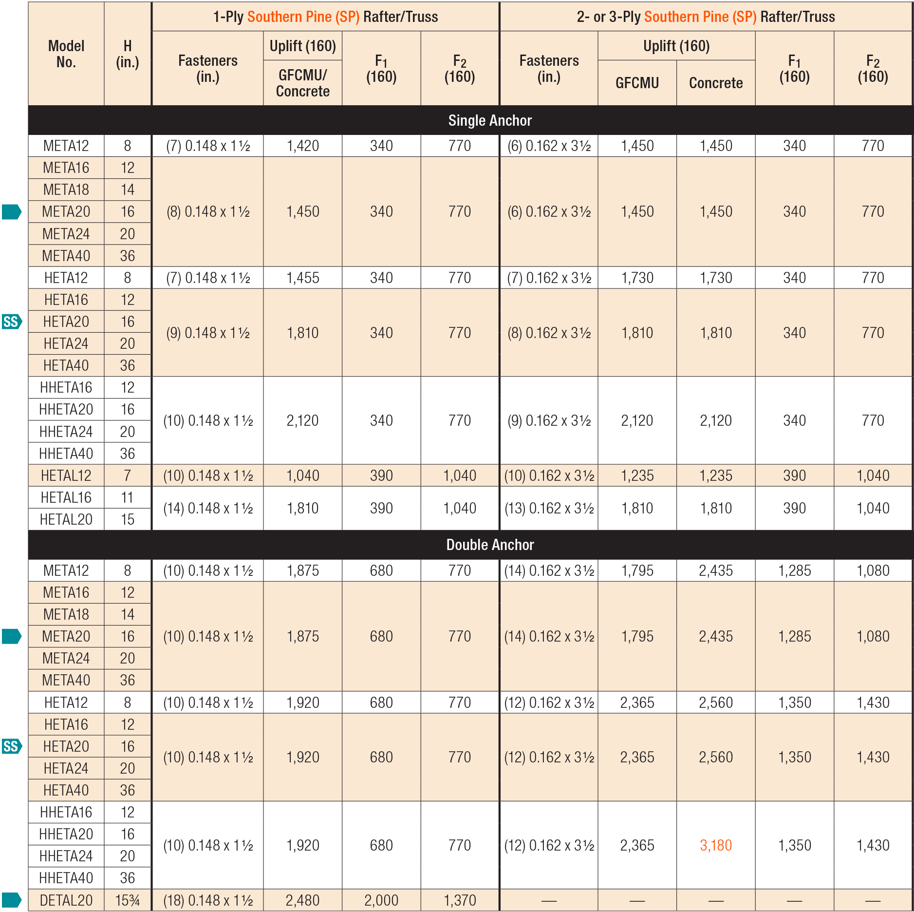
Product Information Tables
Load Tables
These products are available with additional corrosion protection. Additional products on this page may also be available with this option, check with Simpson Strong-Tie for details.
For stainless-steel fasteners, see Fastener Types and Sizes Specified for Simpson Strong-Tie Connectors.
- Loads have been increased for wind or earthquake loading, with no further increase allowed. Reduce where other loads govern.
- Concrete shall have a minimum compressive strength of f'c = 2,500 psi.
- Grout-filled CMU (GFCMU) shall have a minimum compressive strength of f'm = 1,500 psi.
- For simultaneous loads in more than one direction, the connector must be evaluated using the Unity Equation, as described in General Instructions for the Designer.
- F1 lateral load toward face of HETAL is 1,870 lb.
- The HHETA allowable F1 load can be increased to 435 lb. if the strap is wrapped over the truss and a minimum of 12 nails are installed.
- The DETAL20 requires (6) 0.148" x 1 1/2" nails in the truss seat and (6) 0.148" x 1 1/2" nails in each strap. For double META/HETA/HHETA installations, install half of the required fasteners in each strap.
- F1 lateral loads listed for double META/HETA/HHETA on 2- or 3-ply rafter/truss may cause an additional 1/16" deflection beyond the standard 1/8" limit where the straps are installed not wrapped over the heel as shown.
- Minimum edge distance for META/HETA/HHETA is 1 1/2" for concrete and 2" for masonry. Where edge distance is less than 2" for masonry, the maximum uplift load is 1,005 lb.
- It is acceptable to use a reduced number of fasteners provided that there is a reduction in uplift allowable load. Calculate the connector allowable load for a reduced number of nails as follows: Allowable Load = (No. of Nails Used) / (No. of Nails in Table) x Table Load. Lateral loads require the lowest 6 nail holes filled for META and lowest 7 nail holes filled for HETA/HHETA.
- Fasteners: Nail dimensions in the table are listed diameter by length. For additional information, see Fastener Types and Sizes Specified for Simpson Strong-Tie Connectors.


