Description
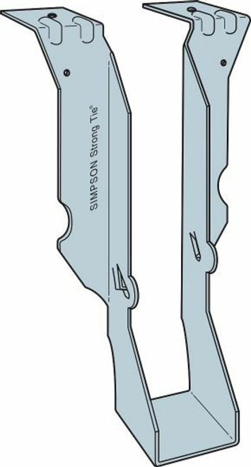
The LBAZ and JBA hangers provide higher loads for 2x10, 2x12 and 2x14 members in 14-gauge and 18-gauge steel, respectively. The nail locations on the JBA enable effective use with nailers.
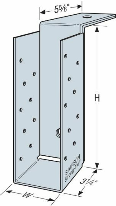
The BA hangers are cost-effective hangers featuring min./max. joist-nailing options. Min. Nailing featuring Positive Angle Nailing targets moderate load conditions whereas the Max. Nailing generates capacities for higher loads. The unique two-level embossment provides added stiffness to the top flange. See tables. See Hanger Options for hanger modifications, which may result in reduced loads.
Material
- JB/JBA — 18 gauge; LB/LBAZ — 14 gauge; BA — 14 gauge or 12 gauge; HB — 10 gauge
- For modified hangers, gauge may increase from that specified for non-modified hangers. Hanger configurations, height and fastener quantity may increase from the tables depending on joist size, skew and slope. Embossments may be omitted.
Finish
- BA, HB, JB, JBA, LB and LBAZ — galvanized; BA, HB and LB may be ordered hot-dip galvanized; specify HDG.
Installation
- Use specified fasteners; see General Notes and nailer table notes.
- LB, LBAZ, HB and BA may also be welded to steel headers with weld size to match material thickness. The minimum required weld to the top flanges is 2" (1 7/16" for LBAZ) fillet weld to each side of each top flange tab. Distribute the weld equally on both top flanges. Welding cancels the top and face nailing requirements. Consult the code for special considerations when welding galvanized steel. The area should be well-ventilated (see General Instructions for the Installer, note k for welding information). Weld on applications produce the maximum allowable download listed. For uplift loads refer to technical bulletin Top-Flange Hangers Welded to Structural Steel Members (T-C-WELDUPLFT).
- Ledgers must be evaluated for each application separately. Check TF dimension, nail length and nail location on ledger.
- For modified hangers, fastener quantity may increase from the tables depending on joist size, skew and slope.
- Bevel cut the carried member for skewed applications.
Options
- See modification tables for allowed options and associated load reductions
Load Tables
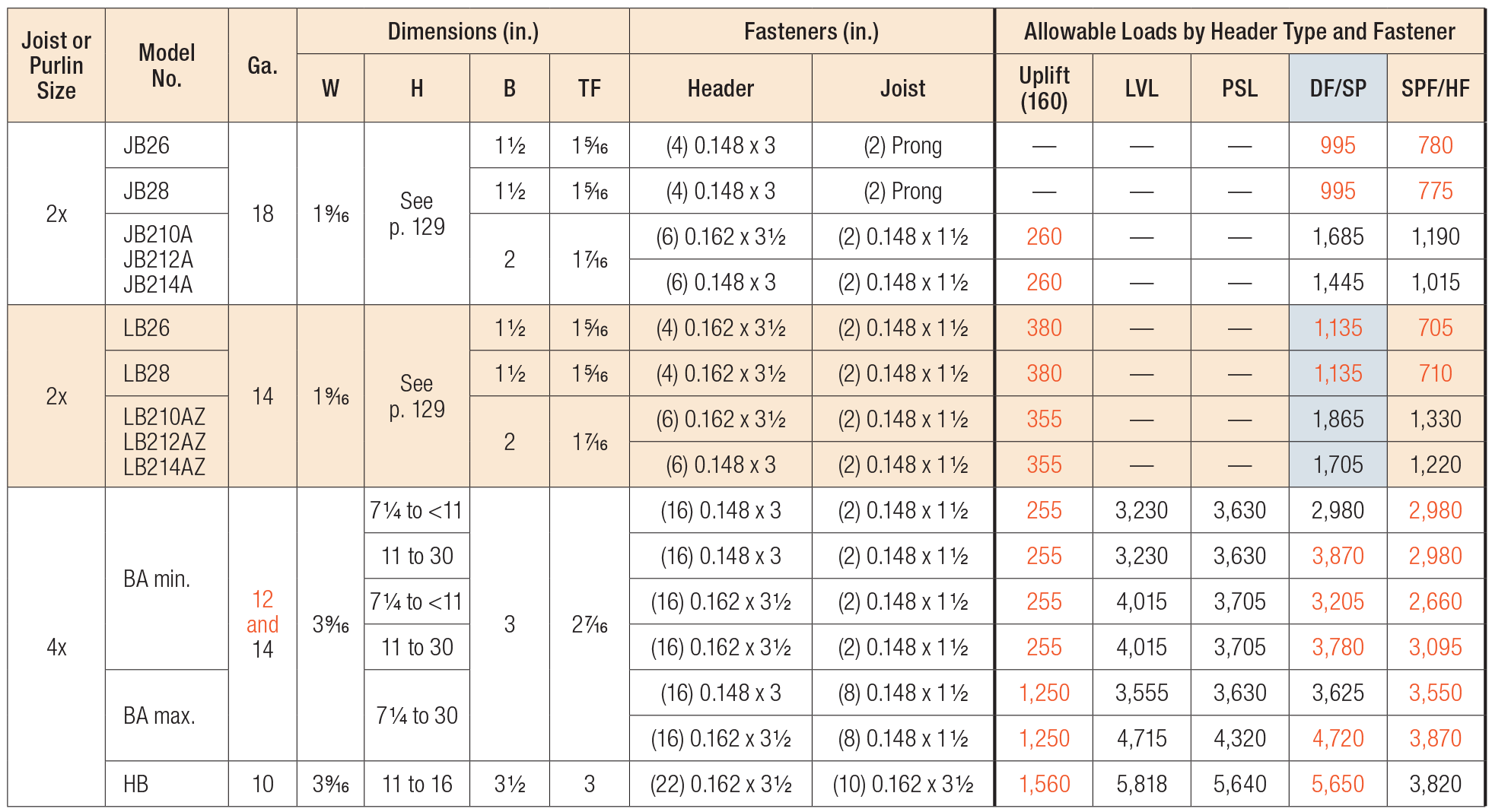
See Top Flange Hanger tables.
See Hanger Options for hanger modifications, which may result in reduced loads.
Various Header Applications

- Uplift loads have been increased for earthquake or wind loading with no further increase allowed. Reduce where other loads govern.
- Uplift loads are based on DF/SP lumber. For SPF/HF, use 0.86 x DF/SP uplift load.
- Uplift loads are based on DF/SP. For SPF/HF, use 0.86 x DF/SP Uplift Load for products requiring nails and 0.72 x DF/SP Uplift Load for products requiring screws.
- Where noted for single-ply joist hangers, use (6) 0.148" x 1 1/2" nails.
- Fasteners: Nail dimensions in the table are listed diameter by length. For additional information, see Fastener Types and Sizes Specified for Simpson Strong-Tie Connectors.
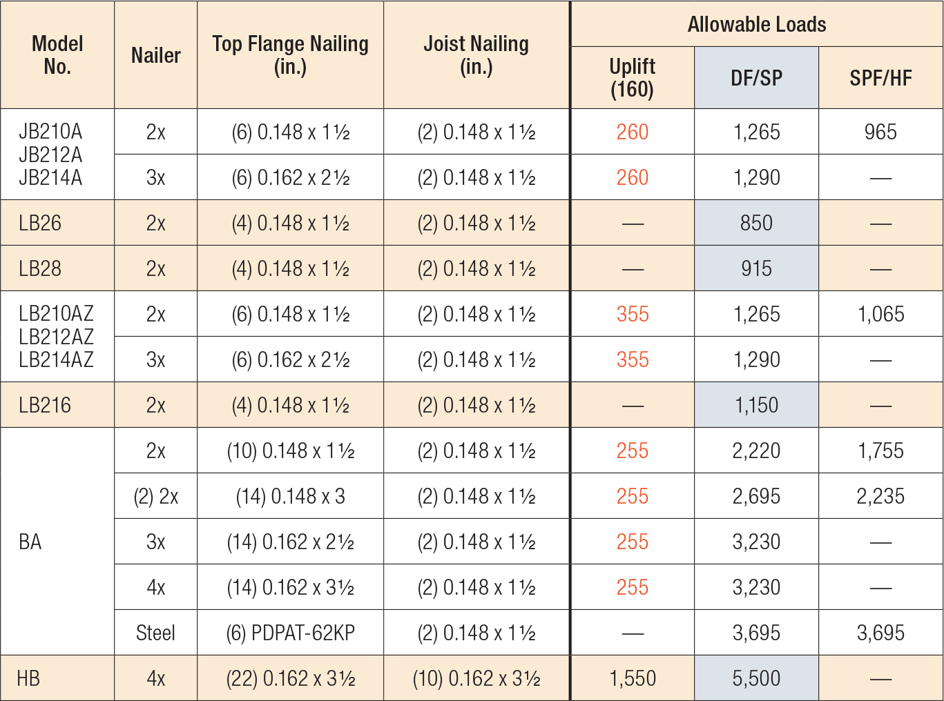
Nailer Table

- Uplift values are for DF/SP nailers only. Refer to technical bulletin T-C-NAILUPLFT for SPF values.
- For joist members 2 1/2" or wider, 0.162" x 2 1/2" joist nails should be installed for additional uplift loads on the 3x and 4x nailer applications of 970 lb. and 1,010 lb. respectively.
- See technical bulletin T-C-NAILUPLFT for increased uplift loads with alternative nailing.
- Attachment of nailer to supporting member is by the Designer.
Modifications and Associated Load Reductions

- Reduction factors are not cumulative. Use the lowest factors that apply.
Reduction Factor Instructions
Allowable Download = Lower of (Seat or Top Flange) x (Table Load)
Allowable Uplift
= 0.90 x (Table Load) for BA with W < 2 1/2"
= 0.71 x (Table Load) for HB with W < 2 1/2"
= 1.00 x (Table Load) for all others


