


Description
Simpson Strong-Tie offers a dedicated range of top-flange I-joist hangers that meet the unique needs of I-joists while offering superior performance and ease of installation.
ITS
The innovative ITS sets the standard for engineered wood top-flange hangers. The ITS installs faster and uses fewer nails than any other EWP top-flange hanger. The Strong-Grip™ seat and Funnel Flange™ features allow standard joist installation without requiring joist nails, resulting in the lowest installed cost. The Strong-Grip seat firmly secures I-joists with flange thicknesses from 1 1/8" to 1 1/2".
MIT/HIT — Positive-Angle Nailing (PAN)
PAN is specifically designed for I-joists when used with the MIT or HIT. With PAN, the nail hole material is not removed, but is formed to channel and confine the path of the nail at approximately 45°. PAN minimizes splitting of the flanges while permitting time-saving nailing from a better angle. See top-flange hanger tables.
Refer to joist manufacturer's literature or appropriate Simpson Strong-Tie Connector Selection Guide for actual joist sizes.
Material
- ITS — 18 gauge; MIT, HIT — 16 gauge
Finish
- Galvanized
Installation
- Use all specified fasteners. Verify that the header can take the required fasteners specified in the table.
- See product-specific installation drawings.
- ITS — no joist nailing required for standard I-joist installation without web stiffeners. When supporting I-joists with web stiffeners or rectangular SCL member (2) 0.148" x 1 1/2" must be installed into optional triangle joist nail holes for standard installation values.
- ITS — optional triangle nail holes may be used for additional load. See allowable load tables.
- MIT — optional triangle nail holes may be used for increased uplift capacity. See Optional Nailing for Increased Uplift table.
- HIT — closed PAN nail holes may be used for increased uplift capacity. See Optional Nailing for Increased Uplift table.
- For sloped joists up to 1/4:12 there is no reduction; between 1/4:12 and up to 1/2:12, tests show a 10% reduction in ultimate hanger strength. Local crushing of the bottom flange or excessive deflection may be limiting; check with joist manufacturer for specific limitations on bearing of this type.
Allowable Loads
- The ITS, MIT and HIT hangers have locations for optional nails if additional uplift is needed. Optional uplift nailing requires the addition of properly-secured web stiffeners. See the load tables for minimum required fasteners and allowable uplift loads.
- For attaching to multi-ply headers, refer to technical bulletin Top-Flange Hanger Reductions for Multiple-Ply Headers (T-C-MPLYHEADR).
Options
- Because these hangers are fully die-formed, they cannot be modified. However these models will normally accommodate a skew of up to 5°.
Load Tables
ITS Series with Various Header Applications
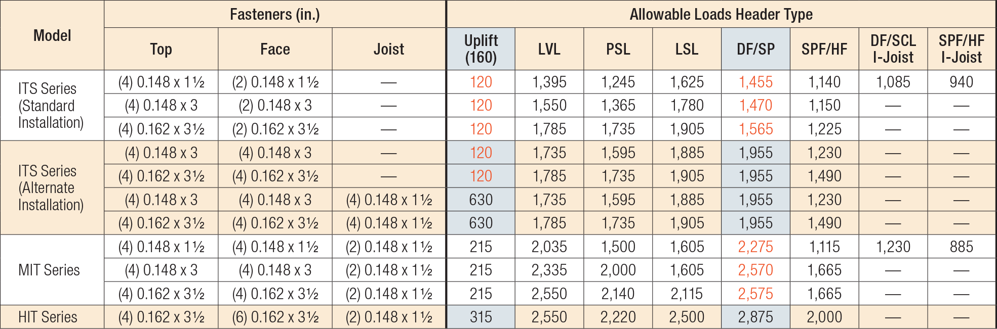
- Loads may not be increased for duration of load.
- Uplift loads have been increased for earthquake or wind loading with no further increase allowed. Reduce where other loads govern.
- Uplift loads are based on DF/SP lumber. For SPF/HF, use 0.86 x DF/SP uplift load.
- ITS uplift loads are valid for all lumber species and need not be reduced for duration of load.
- LVL headers are assumed to be made primarily from Douglas fir or southern pine. For LVL made from spruce-pine-fir or similar less-dense veneers, use the values found in the SPF/HF column.
- DF I-joists headers include flanges made from solid sawn Douglas fir, LVL made primarily of DF/SP, or LSL. For header flanges with thicknesses from 1 5/16" to 1 3/8", use 0.85 of the I-joist header load. For header flanges with thicknesses from 1 1/8" to 1 1/4", use 0.75 of the I-joist header load.
- SCL (structural composite lumber) is LVL, LSL, and Parallam® PSL.
- Web stiffeners required for the ITS Alternate Installation when installing optional joist nails for additional uplift load.
- Code values are based on DF/SP header species.
- I-joists with flanges less than 1 5/16" thick used in combination with hangers thinner than 14 gauge may deflect an additional 1/32" beyond the standard 1/8" limit.
- For 2 1/4"-wide joists, see Top-Flange Hangers Load Tables for allowable loads.
Optional Nailing for Increased Uplift
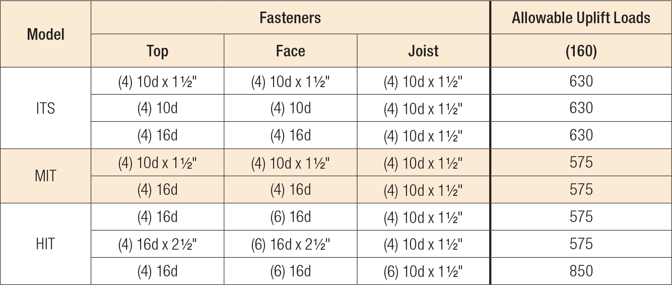
- Uplift loads have been increased for earthquake or wind loading with no further increase allowed. Reduce where other loads govern.
- Uplift loads are based on DF/SP lumber. For SPF/HF, use 0.86 x DF/SP uplift load.
- Web stiffeners are required on I-joist for additional nailing.
Nailer Table
This table indicates various allowable loads for ITS/MIT/HIT hangers used on wood nailers. The header nail type must be substituted for those listed in other tables. See technical bulletin T-C-NAILUPLFT for other uplift values and options.
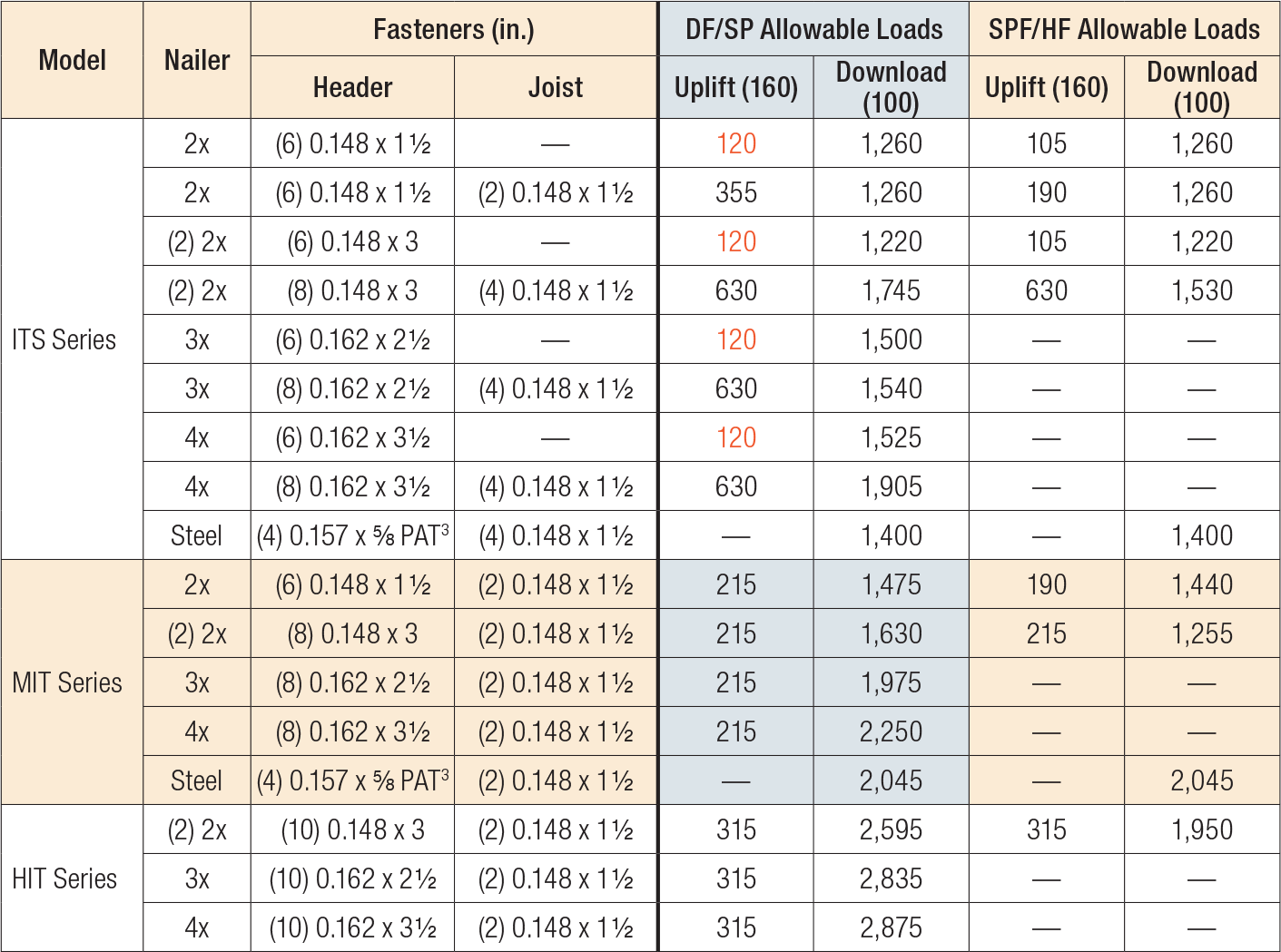
- Uplift loads have been increased for earthquake or wind loading with no further increase allowed. Reduce where other loads govern. See technical bulletin T-C-NAILUPLFT for additional information.
- Steel nailer allowable loads apply to steel header material with thickness between 1/4" and 3/4" with minimum Fy = 36 ksi. Design of steel header by Designer.
- 0.157"-diameter x 5/8"-long powder-actuated fastener = PDPAT-62KP. A red (level 5) or purple (level 6) load may be required to achieve specified penetration.


