


Description
The Simpson Strong-Tie Strong-Drive SDS Heavy-Duty Connector screw is a 1/4"-diameter high-strength structural screw ideal for various connector installations as well as wood-to-wood and engineered wood applications. It installs with no predrilling and has been extensively tested in various applications. The SDS is improved with an easy-driving Type-17 point and a corrosion-resistant double-barrier coating.
The SDS Strong-Drive 1/4" wood screw line has expanded to include stainless-steel SDS screws in 1 1/2" to 3 1/2" lengths, suitable for fastening Simpson Strong-Tie stainless-steel products. Offering the same easy-driving, split-reducing installation of the standard SDS screw, these screws are made from Type 316 stainless steel. The stainless-steel SDS screws are appropriate for higher-exposure environments where maximum corrosion-resistance is required.
Key Features
- Available with a double-barrier coating and Type 316 stainless steel
- Type-17 point (coated and stainless versions) enable easy driving with no predrilling and minimal wood splitting
- 3/8" hex head with 0.48" integrated washer
- Head is stamped with the Simpson Strong-Tie "≠" sign and fastener length for easy identification after installation
- Replacement driver bit — BITHEXR38-134
Applications
- Heavy-duty Simpson Strong‑Tie connectors
Installation
- Install Tip: A low-speed 1/2" drill with a 3/8" hex driver is the recommended tool for installation
Options
- SDS25312SS-R25L, SDS25312-R25L and SDS25500-R25L packaged in a ledger-specific box with 3/8" hex-driver bit
Load Tables
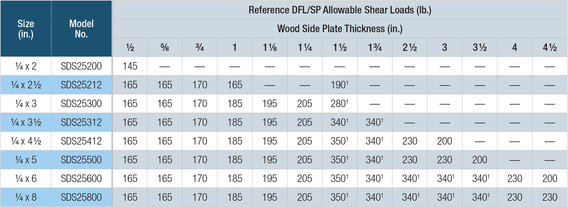
SDS — Allowable Shear Loads — Douglas Fir–Larch and Southern Pine Lumber
SDS — Allowable Shear Loads — Spruce-Pine-Fir and Hem-Fir
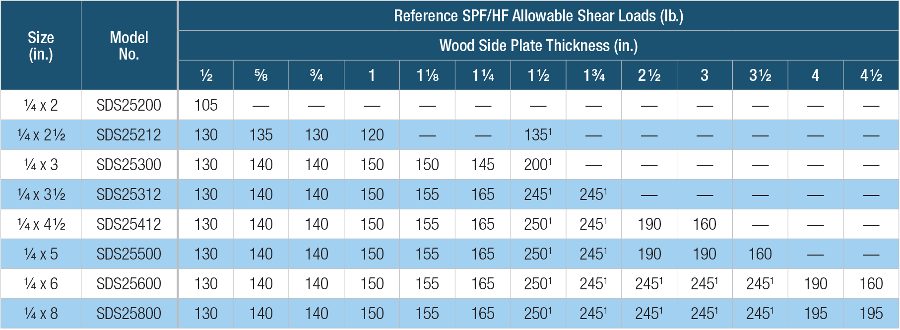
- Noted loads are based on testing per ICC-ES AC233 and assume a minimum main member thickness of the screw length minus the side member thickness. All other allowable loads are based on the NDS and a minimum penetration of 6D = 1.45" into the main member.
- Values are valid for a connection involving only two members. Where the side and main members have different specific gravities, the lower specific gravity shall be used.
- Allowable loads are also applicable to structural composite lumber (e.g., LVL, PSL, and LSL) having an equivalent specific gravity of 0.50 or greater.
- Allowable loads are shown at the wood load duration factor of CD = 1.00. Loads may be increased for load duration by the building code up to a CD = 1.60. The Designer shall apply all adjustment factors required per NDS.
- Loads are based on perpendicular installation into the side grain of the wood members.
- Loads apply to corresponding stainless-steel models.
- For in-service moisture greater than 19% use CM = 0.7.
SDS — Allowable Shear Loads — Installations into the Narrow Face of 2X SPF, HF, DFL, SP Lumber
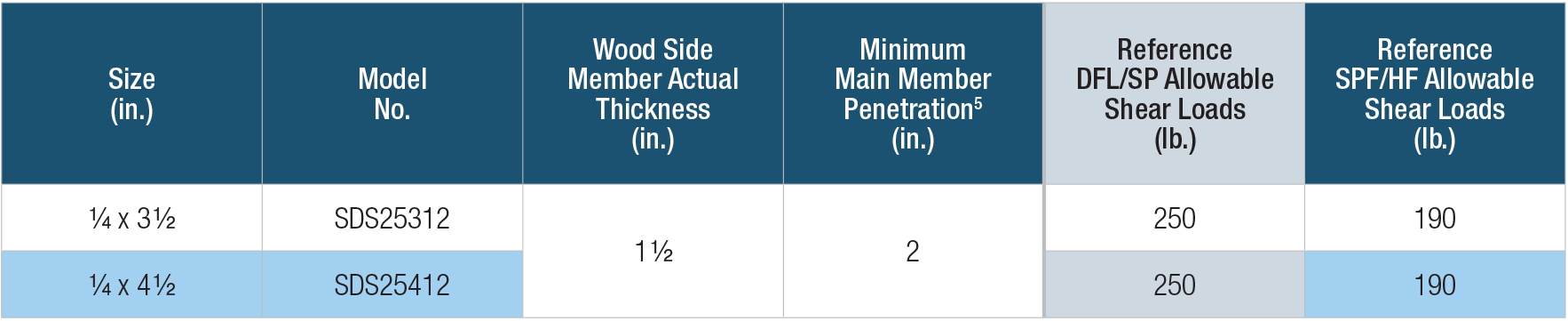
- Allowable loads are based on testing per ICC AC233 and are limited to parallel-to-grain loaded solid-sawn main members (2" nominal). Wood side members may be loaded parallel or perpendicular to grain (see footnote 4).
- DFL/SP allowable loads are based on wood members having a minimum specific gravity of 0.50, and SPF/HF allowable loads are based on wood members having a minimum specific gravity of 0.42. Where the side and main members have different specific gravities, the lower values shall be used.
- Allowable loads are shown at the wood load duration factor of CD = 1.00. Loads may be increased for load duration by the building code up to a CD = 1.60.
- Minimum spacing of fasteners is 3" o.c., minimum end distance is 3" for all parallel-to-grain loaded members, or 4" for all perpendicular-to-grain loaded members, and minimum edge distance is 3/4" for all parallel-to-grain loaded members, or 1 1/2" for perpendicular-to-grain loaded side members.
- Screws may be installed with an intermediate layer of wood structural panel between the side and main member provided the wood structural panel is fastened to the main member per code and the minimum penetration of the screw into the main member (excluding the wood structural panel) is met.
SDS — Allowable Shear Values for Sole-to-Rim Connections
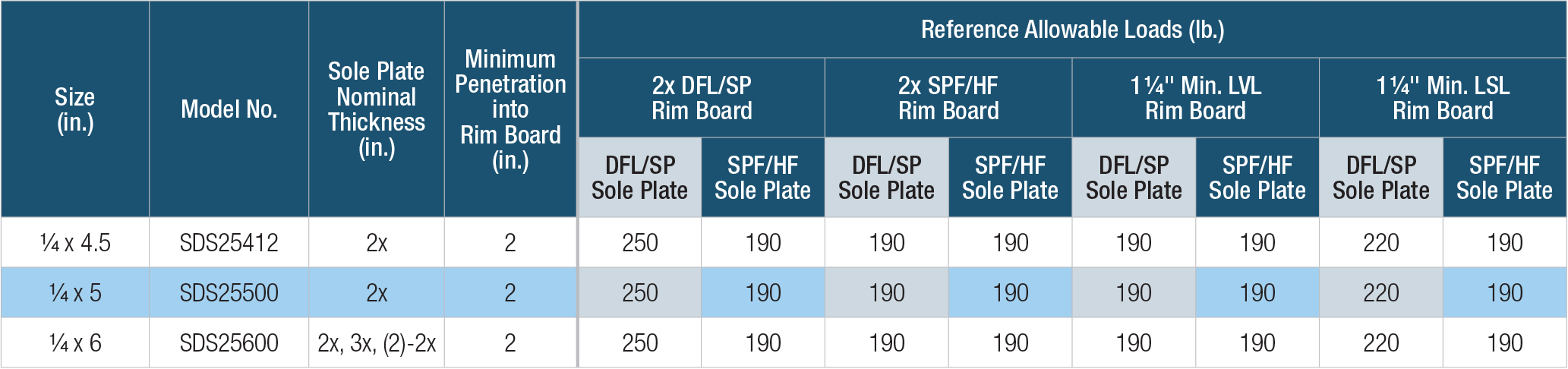
- Allowable loads are based on testing per ICC-ES AC233 and are limited to parallel-to-grain loading.
- Allowable loads are shown at the wood load duration factor of CD = 1.00. Loads may be increased for load duration by the building code up to a CD = 1.60.
- Minimum spacing of the SDS for sawn lumber applications is 3" o.c., minimum end distance is 3", and minimum edge distance is 5/8".
- Minimum spacing of the SDS for LVL and LSL applications is 6" o.c., minimum end distance is 6", and minimum edge distance is 5/8".
- Wood structural panel up to 1 1/8" thick is permitted between the sole plate and rim board provided it is fastened to the rim board per code and the minimum penetration of the screw into the rim board is met.
- A double 2x sole/top plate is permitted provided it is independently fastened per the code and the minimum screw penetration per the table is met.
- Minimum rim board height shall be 9 1/4" when using SDS screws for sole and top plate fastening.
- Sole-to-rim loads can be achieved without a wall below.
2015 and 2018 IRC Compliant Spacing for a Sawn Lumber Deck Ledger-to-Rim Board
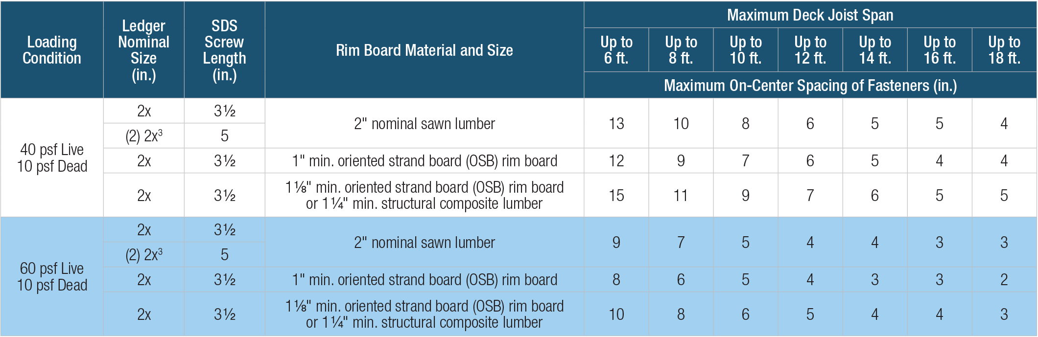
- Solid-sawn rim board shall be spruce-pine-fir, hem-fir, Douglas fir–larch, or southern pine species. Ledger shall be hem-fir, Douglas fir–larch, or southern pine species.
- Fastener spacings are based on single fastener testing of the Strong-Drive SDS screw with a safety factor of 5.0 and include NDS wet service adjustment factor.
- Multiple ledger plies shall be fastened together per code independent of the SDS screws.
- SDS screw spacing values (above) are equivalent to 2018 IRC Table R507.9.1.3(1) and 2015 IRC Table R507.2, based on testing of the Strong-Drive SDS screw with a factor of safety of 5.0. The table above also provides SDS screw spacing for a wider range of materials commonly used for rim board, and an alternate loading condition as required by some jurisdictions.
- Screw models SDS25312, SDS25312SS and SDS25500.
SDS — Allowable Shear Loads — Steel Side-Plate Applications
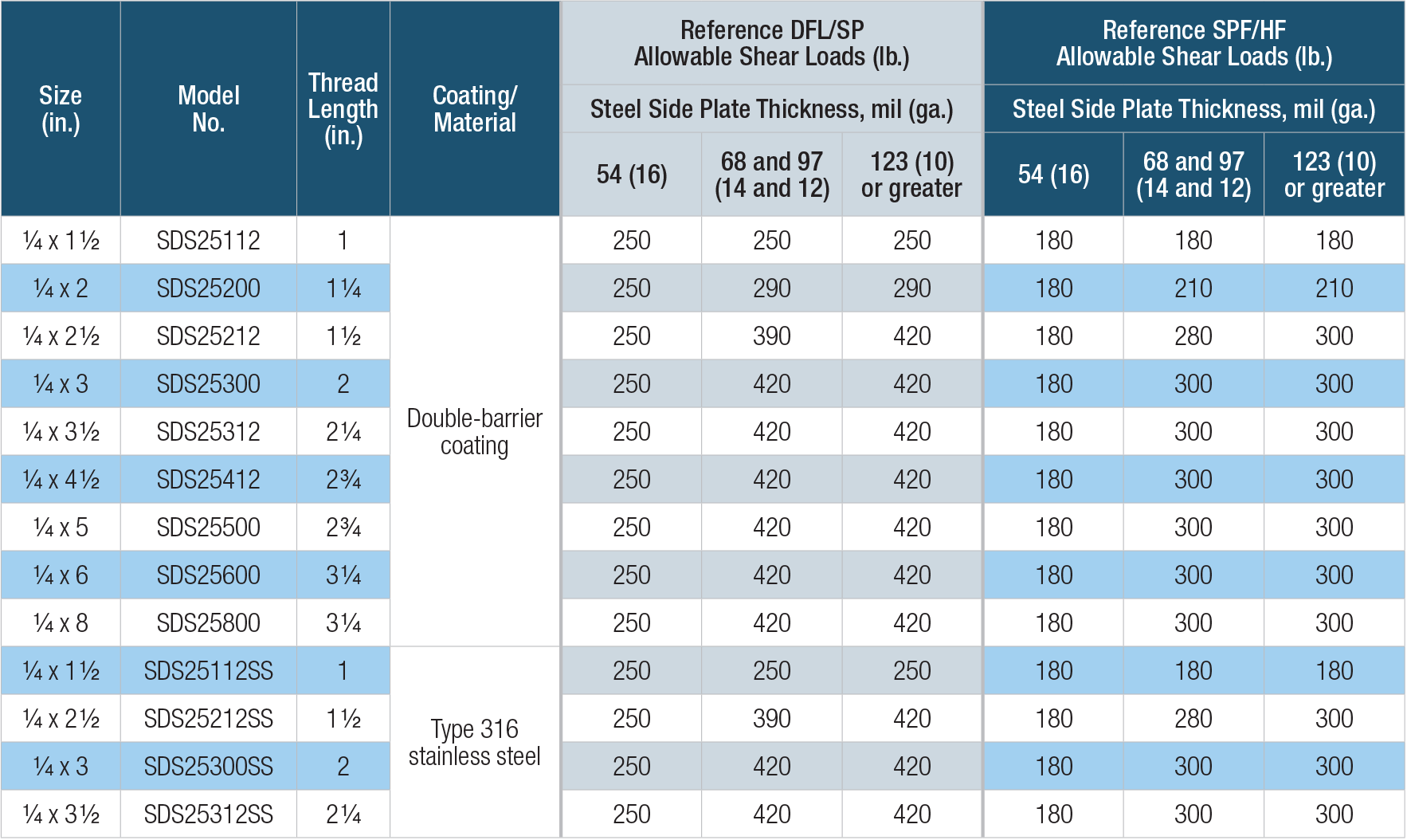
- Allowable loads are shown at the wood load duration factor of CD = 1.00. Loads may be increased for load duration up to a CD = 1.60.
- Allowable withdrawal load for DFL/SP/SCL is 172 lb./in. and for SPF/HF withdrawal is 121 lb./in. Total withdrawal load is based on actual thread penetration into the main member.
- LSL wood-to-wood applications that require 4 1/2", 5", 6" and 8" SDS screws are limited to interior-dry use only.
- Minimum spacing requirements are listed in ICC-ES ESR-2236.


